|
|
Post by RuckusNation on Jan 18, 2013 12:44:59 GMT -5
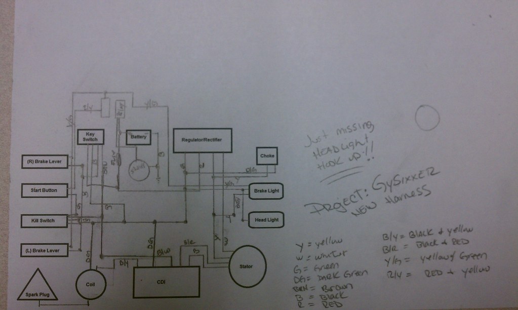
This was the diagram i designed and used for my last scooter. This deleted the alarm system, blinker lights, running lights, and had my headlights hooked to a switch so i can shut them off during the day.
Also, best thing to do is go thru all the wires and SOLDER and HEATSHRINK them. No wire crimps. Makes the connections so much better!!!
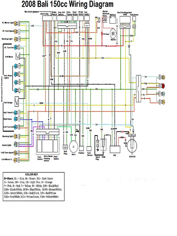
[sorry for the poor quality pic]My diagram  Actual diagram 
|
|
|
|
Post by RuckusNation on Jan 18, 2013 12:52:47 GMT -5
This was also helpful when i needed to wire my scooter..
Now lets start with the R/R and the ignition key switch.
On the R/R you need to bolt it in place on the frame where you want to and it should have 4 wires plugging in to it;
Red = charging wire to battery
White = AC feed from engine stator to R/R
Yellow = AC feed to engine stator to R/R
Green = ground
The red wire will be run directly to the battery's positive terminal.
The white wire goes from the R/R to the white wire on your engine from the stator
The yellow wire will go from the R/R to the engine stator
The green wire will go from the R/R to the engine stator ....AND to the frame at the point of where you hook the black negative cable from the battery. Make sure the frame is clean of paint and these connections are good. YOU ALSO HAVE A BLACK cable from the same frame connection going to the engine to GROUND the engine. Very important that the engine is properly grounded. YOU MAY ALSO have a black ground wire coming from the frame ground point to a bolt on the fan cover right by the oil dip stick again a very important ground wire.
Now the YELLOW wire will be spliced into for the tail/head lights and we'll talk about that later.
Now the igniting key switch, it will have four wires that we will use;
Red = FUSED wire from the positive post of the battery
Black = 12VDc power feed when key is in the ON position
Green = ground
Black/white = engine kill wire to the CDI
Run the red feed wire from the positive battery post to the red wire location to the key switch again this wire needs to be FUSED with at least a 15A fuse.
Since you are not using any accessories run the black wire to each black wire on the brake handle switches and that's it.
Run the black/white wire to the correct plug in spot on the CDI to the correct spot on the key switch.
The green wire is ground and you need a good ground wire from the frame grounding point to the key switch correct location also. YOU WILL also splice into this ground wire for the engine start button and the emergency kill switch if you keep it?
Now lets hook up the brake lights and starter relay. The brake light wire is the yellow/green wire in the harness. It hooks up to both brake light switches also and carries the 12VDc power supplied by the black wire to each switch.
The yellow/green wire also splits and goes to one side of the starter relay so when you press the brake you send 12 Vdc power to the brake light bulb and the starter relay at the same time, this is a safety feature so you must have a brake on when starting the scooter.
Now the yellow/green goes all the way back to your brake/tail light/s and you also have two other wires there a green=ground which again must hook to the frame grounding point and a brown wire for your tail light/s.
Now while you are doing this lets do the other side of the bulb/s the tail lights = brown wire.
Tie the brown wire into the yellow wire on the R/R. If you are going to keep the license plate light tie the brown wire on it to the brown wire on the tail light circuit and ground the green wire.
When you start the scooter the tail lights and license plate light will be on at all times.
Now lets go back to you start button and emergency kill switch. I will give you two options just a start button with no kill switch or both.
Just a start button simply run the yellow/red to the other side of the starter relay opposite the yellow/green wire and the green wire to a ground. The scooter will only start when you turn the key on, press the brake handle and then hit your start button.
REMEMBER THE START BUTTON supplies the ground side to the starter relay.
Now if you are going to use the emergency kill switch we do this. You see it has two green grounds a black/white and a green jumper to the engine start button.
This system does two things, with the switch in the engine off position it grounds out the CDI just like the key switch does through the same black/white wire and at the same time opens the ground circuit to the start button. Not only with the CDI grounded out will you get no spark the engine will not make a sound when you push the start button, you have no ground wire to the start button!
So if you want to keep the emergency kill switch leave the jumper wire from it to the start button and hook both greens to ground and the black/white kill wire to the same black/white kill wire on the key switch that runs to the CDI.
Speaking of the CDI it has two plugs a 3-wire plug and a 2-wire plug, leave them as they are and just make sure the wires on it run back to the places they are now and either loop any excess wire up out of the way or cut the excess out and splice accordingly.
Now that leaves us now with the headlight/s Again I'll give you two options. You currently have them run to the battery, that's a no no, it'll run the battery down and they need to run from the R/R . If the R/R doesn't have a adequate load on it it'll try to shunt the excess voltage to ground, simply put it'll be short lived.
If you are going to use your current headlight switch then you simply need to run the wire from the switch which will be either yellow or brown to the yellow wire on the R/R and hook the other wires off of the switch to the current ones now and all will be well, you have hi and or lo beams.
Also if you are going to use this switch you may have what is called a passing switch and if you do there will be a black wire to your switch. If you use this switch and want this passing light then simply tie this black wire to the black wire off of the key switch, the same wire the brake light wires are hooked up to.
Now if you don't want to use this switch and want to use a simple on/off toggle switch then go buy one and I would get a heavy duty one rated for at least 30A.
Now I'm presuming that your headlight wire colors are
dark blue = hi beams
pink or white = lo beams
Now remember to run off of the R/R we must tie into the yellow wire on the R/R the same one we tied our tail light/s to.
Run a yellow or brown wire from the yellow R/R wire to one side of your on/off toggle switch. Take the lo beam wire pink or white and put it on THE SAME TERMINAL as the wire you just hooked up from the yellow wire on the R/R.
Now this makes a direct wire connection and when you start the scooter the lo beams will be on just like your tail light/s. This gives the R/R the proper load it needs to work properly.
Now what about the hi beams? Tie the dark/blue on the other terminal of your new on/off toggle switch. When you turn it to the on position the hi beams will come on with the lo beams that are already on.
You will not be able to have this passing light function unless you get a spring loaded on/off push button and then tie one side to the dark/blue hi beam wire and the other side will go to the black key ignition wire.
Also remember your headlight/s will have a green = ground wire run to them.
Now to trouble shoot the starter relay it's simple. When you get your wires run and routed like you want simply turn on the key, press a brake handle ( use a rubber band to hold it on) press the start button.
Take your volt meter and unplug the relay and put one lead on the yellow/green the other lead to the red/yellow, set the meter to 20 or higher DC and if it is working correctly you will read 12Vdc or higher depending on your battery strength. If you read 12Vdc and the relay still will not kick in the relay is bad , REPLACE.
Now if you get no voltage then here is a list of possible problems;
Bad brake switch/s not passing 12Vdc power, if your brake light/s come on then rule this out
Bad or broke wire to relay, red/yellow or yellow/green can ohm each wire for continuity.
Bad start button, can ohm of this
Bad ground wire to start button again can ohm for this.
|
|
|
|
Post by cobbinator on Oct 21, 2023 12:19:46 GMT -5
Very well put,sir
|
|